Are you looking for a simple and reliable hazard light circuit for your DIY projects, bicycle, or remote-controlled cars? In this step-by-step tutorial, we will learn how to build a Super Easy Hazard Light LED Circuit from scratch without using any complicated Integrated Circuits (ICs) like the 555 Timer!
This circuit uses basic electronic components like a relay and a capacitor to create a perfect flashing hazard light effect. It is cost-effective, beginner-friendly, and takes less than 10 minutes to build.
🛠️ Required Components List
Before starting the wiring, make sure you have the following basic electronic components ready. You can easily find them in any local electronics shop or salvage them from old devices.
| Component Name | Specification / Value | Quantity |
| Relay | 12V DC Relay | 1 |
| Capacitor | 6800µF (Electrolytic) | 1 |
| Resistor 1 | 82 Ohm | 1 |
| Resistor 2 | 1K Ohm | 1 |
| LEDs / Bulbs | 12V Indicator Bulbs / Bright LEDs | 2 |
| Indicator LEDs | Small Red/Green LEDs | 2 |
| Diodes | IN4007 or similar | 2 |
| Buzzer | 12V DC Piezo Buzzer | 1 |
| Switches | SPST Toggle Switch / Push Button | 2 |
| Power Source | 12V DC Battery | 1 |
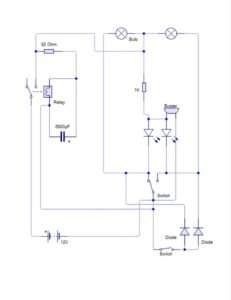
🔌 Complete Circuit Diagram & Wiring Schematic
📝 Step-by-Step Connection Guide
To make this flashing mechanism work flawlessly without a timer IC, we are utilizing the charging and discharging property of a high-value capacitor combined with a relay loop:
-
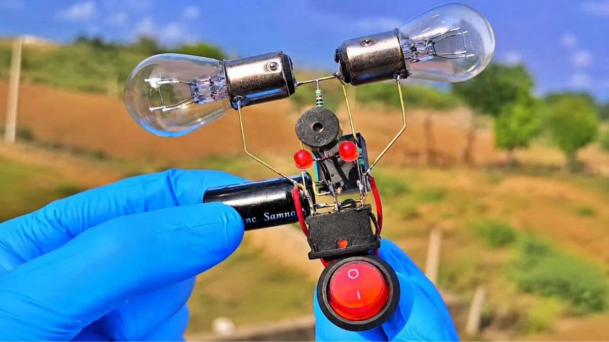
The Relay Loop: Connect the 82 Ohm resistor in parallel with the relay coil. Place the massive 6800µF capacitor across the relay coil terminals. Ensure the correct polarity (+ and -) of the capacitor.
-
Main Power Switch: Connect the 12V DC Battery’s positive terminal to the main toggle switch, leading directly into the relay’s common pin.
-
The Flashing Action: When power is applied, the capacitor charges up, triggering the relay coil. As soon as the relay switches, it breaks its own charging path, causing the capacitor to discharge and release the relay. This loop repeats infinitely, creating a perfect automatic flashing effect!
-
Output Indicators & Buzzer: Connect the alternating output terminals to your main 12V bulbs, parallel indicator LEDs (with 1K protection resistor), and the 12V piezo buzzer to get an audio-visual blinking hazard alert.
⚙️ How This Circuit Works (Without IC)
Most automatic flashing or blinking circuits rely heavily on electronic timers like the NE555 IC. However, this configuration relies purely on electromechanical switching.
When you toggle the main switch, the 12V power source instantly rushes to charge the 6800µF electrolytic capacitor. Once the capacitor builds up enough charge, its voltage reaches the threshold required to energize the relay’s internal electromagnet coil. The relay switches its internal contact contacts immediately.
Because of the clever wiring, this switching action instantly disconnects the main power supply feeding the capacitor. Now disconnected from the battery, the relay coil starts pulling current directly from the stored energy inside the capacitor. As the capacitor completely discharges its remaining power, the relay coil loses its magnetic field, snapping back to its original resting position. This immediately restores the battery connection, charging the capacitor once again and repeating the cycle continuously.
🚀 Real-World Applications
This incredibly robust, easy-to-build circuit has several practical applications across various hobbyist electronics and hardware safety systems:
-
Bicycle & Motorcycle Safety: Can be implemented as an emergency hazard light system or secondary breakdown blinker.
-
RC Vehicles & Toys: Perfect for adding realistic indicator flashing signals and audio alerts to remote-controlled cars, trucks, or custom robotics projects.
-
Electronic Models: Ideal training tool for engineering students to understand high-capacity capacitor discharge dynamics without dealing with delicate digital chips.
📥 Download Complete PDF Schematic & Layout Guide
If you want to save this clean circuit design layout for your offline workshop, or if you need the full high-resolution documentation and raw wiring charts, you can access the fast download mirror below.
Note: Clicking the button will forward you securely to our high-speed download server directory.
Click the button above to request secure download link.